
No products
DIY Electronic KIT
- DRONES
- HELIS
- PLANES
- CARS
- BOATS
- SPARE PARTS
- QUAD COPTERS
- MICRO QUAD PARTS
- ALIGN M424 Quadcopter
- Quanum/CX-20/ DJI PARTS
- Cheerson CX-33 Parts
- Cheerson CX-35 parts
- freeX Parts
- SYMA X5 PARTS
- SYMA X8 PARTS
- HUSBAN PARTS
- WLtoys PARTS
- Tarantula X6
- Q-BOT PARTS
- Zoopa Q parts
- Eachine
- VISUO XS809/XS816 parts
- Eachine E58 PARTS / X-PRO
- VISUO XS812 GPS parts
- SHRC H1G GPS PARTS
- Eachine Tyro99
- Wltoys XK X1
- FUNSKY S20 PARTS
- Eachine E520S GPS PARTS
- Eachine E511S GPS PARTS
- Eachine Tyro79 parts
- Eachine EG16 parts
- Eachine Tyro129 parts
- Eachine Tyro109 parts
- Eachine Tyro69 parts
- JJRC X16 5G parts
- Eachine Tyro89 parts
- ΕΛΙΚΟΠΤΕΡΑ
- ALIGN
- ESKY
- E-FLITE
- TAROT (100% COPY ALIGN)
- WALKERA
- Walkera 38 Parts
- Walkera 4-3B/4-3Q2 Parts
- Walkera 5-10 Parts
- Walkera 5-6 Parts
- Walkera 53-1 Parts
- Walkera 5G6 Parts
- Walkera LAMA2 Parts
- Walkera UFO 5 Parts
- Walkera 4G3 Parts
- Walkera Metal Upgrade Parts
- Walkera 5G6-1 Parts
- Walkera 5G4Q3 Parts
- WALKERA 5-4,5,8 PARTS
- Walkera 53Q3 PARTS
- Walkera UFO8 Parts
- Walkera LAMA 400 Parts
- WALKERA LAMA2Q PARTS
- WALKERA LAMA2Q1 PARTS
- WALKERA UFLY
- Walkera 4G6
- SKYARTEC
- SKYA
- Hisky
- Wltoys
- ARK
- HK
- THUNDER TIGER
- GAUI
- ELE
- OUTRAGE
- COPTER X
- HDX
- Copter V-MAX Parts
- Copter Mini X - SH-6025-1
- ACME HELIS
- XK
- Eachine Parts
- XK-WLTOYS
- RC ERA HELIS
- ΑΕΡΟΠΛΑΝΑ
- ΑΥΤΟΚΙΝΗΤΑ
- Accessories
- 1/16 Short Course Truck
- 1/16 Brushless 4WD Racing Buggy
- JJRC Q35/Q36 PARTS
- 9115 parts
- Wltoys A989/A999/L939/K969/K989
- WLtoys A949 A959 A969 A979 PARTS
- Wltoys L959/L969/L979
- Wltoys 144001 parts
- Pxtoys PX9300 1/18
- RC Trailer
- Wltoys 12429 parts
- Eachine EAT04/Feiyue FY01/2/3 1/12 parts
- XLF X03 1/10 PARTS
- Xinlehong 913xx 1/16 PARTS
- Wltoys 12428 parts
- Wltoys 104001 1/10 PARTS
- Wltoys 124017 1/12 PARTS
- Wltoys 124018 1/12 PARTS
- HBX 16886 1/14 4WD PARTS
- HBX 903 RTR 1/12 2.4G 4WD PARTS
- HBX 16889A Pro 1/16 2.4G PARTS
- Wltoys 104009/12402 1/10 PARTS
- Wltoys XK 22201 1/22 parts
- F-20 2.4GHz 1/12 - PARTS
- Wltoys 144010 1/14 PARTS
- Eachine EAT15 Parts
- Wltoys 124010 1/12 PARTS
- Wltoys 284131 1/28 PARTS
- Wltoys 284161 1/28 PARTS
- Wltoys 124008 1/12 PARTS
- Wltoys 284010 1/28 PARTS
- 1/10 HSP PARTS
- Wltoys 184008 1/18 - parts
- WLTOYS 144016 1/14 - PARTS
- BOATS
- BLADES
- RC BEARINGS
- QUAD COPTERS
- RADIOS
- ELECTRONICS
- SPEED CONTROLLERS
- SERVOS
- FPV SYSTEMS
- ΚΑΛΩΔΙΑ & ADAPTERS
- SIMULATORS
- BEC & Regulator
- GADGETS
- ΜΠΟΥΖΟΠΙΠΕΣ
- ΦΩΤΑ & Night Flying
- ACME FlyCams
- ΔΙΑΦΟΡΑ
- BATTERIES & CHARGERS
- MOTOR
- TOOLS-ACCESSORIES
- ΕΡΓΑΛΕΙΑ ΜΕΤΡΗΣΕΩΝ
- ΒΑΛΙΤΣΕΣ
- COVERING FILMS
- ΚΟΛΛΕΣ & ThreadLock
- ΑΕΡΟΓΡΑΦΟΙ
- ΝΤΙΖΕΣ & AΞΕΣΟΥΑΡ
- ΔΙΑΦΟΡΑ ΑΞΕΣΟΥΑΡ
- ΑΞΕΣΟΥΑΡ NITRO
- ΜΠΟΥΖΙ
- ΜΙΖΕΣ
- ΤΡΟΜΠΕΣ ΚΑΥΣΙΜΟΥ
- ΕΡΓΑΛΕΙΑ & ΟΡΓΑΝΑ ΑΚΡΙΒΕΙΑΣ
- ΦΙΛΤΡΑ ΚΑΥΣΙΜΟΥ
- ΒΙΔΕΣ & Washer & E-Clips
- TRAINING KIT
- PITCH GAUGE
- TESTER
- TAPES & VELCRO
- Lubricants & Accessories
- DECALS & STICKERS
- ΕΡΓΑΛΕΙΑ MULTIFUNCTIONAL SKYA
- ΖΥΓΑΡΙΕΣ
- Cleaning Accessories
- Swashplate Leveler
- Starter Shaft
- Glow Ignitors
- DIGITAL MULTIMETERS
- LIGHTNING LED
- SOLDERING IRON
- HAND TOOLS
- DEPRON
- ΚΟΥΤΙΑ ΑΠΟΘΗΚΕΥΣΗΣ
- ΜΠΡΟΣΕΛΕΣ
- ΔΕΜΑΤΙΚΑ
- FOR BEGINNERS
- GADGETS FOR PC
- MAGAZINES & DVD
- SLUBAN BRICKS
- 3D PRINTERS / SCANNERS
- 3D PUZZLES
- ARDUINO - ROBOTICS
- DIY Electronic KIT
 View larger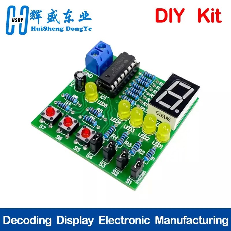
Decoding Display Electronic Manufacturing Loose Parts Training and Teaching Kit DIY Welding Matching Skills Simulation
(SKU): S-39
Decoding Display Electronic Manufacturing Loose Parts Training and Teaching Kit DIY Welding Matching Skills Simulation
In stock
More info
Kit Parameters:
Power supply voltage: 5V (DC power supply)
Board size: 50 * 50mm
Circuit Diagram

CD4511 is a commonly used seven segment display decoding driver. In addition to the seven segment decoding circuit, it also has a latch circuit and an output driver part. It has the characteristic of high output current, up to 25mA driving current, and can directly drive LED digital tubes. CD4511 consists of four input terminals ABCD and seven output terminals a~g. It also has an input BCD code latch terminal LE, a light test LT, and a turn off control terminal BI. Among them, ABCD is the BCD code input, A is the low bit, and the input status can be controlled through S1-S4. When the corresponding switch is disconnected (remove the short-circuit cap), the input is low-level "0". When the corresponding switch is closed (put on the short-circuit cap), the input is high-level "1". LT is the light testing end. When the high level is applied, the display will display normally. When the low level is applied, the display will always display the number "8", and each pen segment will be lit up to check if there is a fault on the display. This function can be tested through S5. BI is the hidden function end, and when the low level is applied, it will display 1234567910112131415AABBCCD DEFG LTBI LEIC1 CD4511 R9 1K R10 1K R11 1K R11 1K R12 1K R13 1K R14 1K R15 1K a bc d ef g dp abc defgdp com Ds1 S4 S3 S2 S1 R11KR21K21 R31KR41K LED1 LED2 LED3 LED4 GNDR51KR61KR71KS7 S6 S5 VCC VCC VCC GND GND 12 JP1 C147uF GND R81KLED5GND816 has all pen segments hidden. When displayed normally, the B1 end should be raised to a high level. This function can be tested through S6. In addition, CD4511 has the characteristic of rejecting pseudocodes. When the input data exceeds the decimal number 9 (1001), the displayed glyph also disappears on its own. LE is the latch control terminal, which locks during high battery levels and transmits data during low battery levels. This function can be tested through S7. A~g is a 7-segment output that can drive a common cathode LED digital tube DS1. R1-R4 and R8-R15 in the circuit are the current limiting resistors of the LED
Product Images


