
Κανένα προϊόν
ΔΙΑΦΟΡΑ
- DRONES
- ΕΛΙΚΟΠΤΕΡΑ
- ΑΕΡΟΠΛΑΝΑ
- ΑΥΤΟΚΙΝΗΤΑ
- ΣΚΑΦΗ
- ΑΝΤΑΛΛΑΚΤΙΚΑ
- QUAD COPTERS
- MICRO QUAD PARTS
- ALIGN M424 Quadcopter
- Quanum/CX-20/ DJI PARTS
- Cheerson CX-33 Parts
- Cheerson CX-35 parts
- FreeX Parts
- SYMA X5 PARTS
- SYMA X8 PARTS
- HUSBAN PARTS
- WLtoys V686 PARTS
- Tarantula X6
- Q-BOT parts
- Zoopa Q parts
- Eachine
- VISUO XS809/XS816 parts
- Eachine E58 PARTS / X-PRO
- VISUO XS812 GPS parts
- SHRC H1G GPS PARTS
- Eachine Tyro99
- Wltoys XK X1
- FUNSKY S20 PARTS
- Eachine E520S GPS PARTS
- Eachine E511S GPS PARTS
- Eachine Tyro79 parts
- Eachine EG16 parts
- Eachine Tyro129 parts
- Eachine Tyro109 parts
- Eachine Tyro69 parts
- JJRC X16 5G parts
- Eachine Tyro89 parts
- ΕΛΙΚΟΠΤΕΡΑ
- ALIGN
- TREX 100 / TREX 100X
- TREX 150 DFC
- TREX 250 / DFC
- TREX 250SE/PRO/DFC
- TREX 450SE/V1/V2/V3
- TREX 450 SPORT/V2/PLUS
- TREX 450 PRO/V2/DFC/3GX
- 450L DOMINATOR Parts
- TREX 500 /ESP/EFL/PRO/3G/DFC
- TREX 550E / PRO / DFC
- TREX 600E / ESP / 3G / PRO / EFL / DFC
- TREX 600N / Limited / 3G
- TREX 700N / Limited / 700E / 3G / DFC / 800E
- ESKY
- E-FLITE
- TAROT (100% COPY ALIGN)
- WALKERA
- Walkera 38 Parts
- Walkera 4-3B/4-3Q2 Parts
- Walkera 5-10 Parts
- Walkera 5-6 Parts
- Walkera 53-1 Parts
- Walkera 5G6 Parts
- Walkera LAMA2 Parts
- Walkera UFO 5 Parts
- Walkera 4G3 Parts
- Walkera Metal Upgrade Parts
- Walkera 5G6-1 Parts
- Walkera 5G4Q3 Parts
- WALKERA 5-4,5,8 PARTS
- Walkera 53Q3 PARTS
- Walkera UFO8 Parts
- Walkera LAMA 400 Parts
- WALKERA LAMA2Q PARTS
- WALKERA LAMA2Q1 PARTS
- WALKERA UFLY
- Walkera 4G6
- SKYARTEC
- SKYA
- Hisky
- Wltoys
- ARK
- HK
- THUNDER TIGER
- GAUI
- ELE
- OUTRAGE
- COPTER X
- HDX
- Copter V-MAX Parts
- Copter Mini X - SH-6025-1
- ACME HELIS
- XK
- Eachine Parts
- XK-WLTOYS
- RC ERA HELIS
- ALIGN
- ΑΕΡΟΠΛΑΝΑ
- ΑΥΤΟΚΙΝΗΤΑ
- Accessories
- 1/16 Short Course Truck
- 1/16 Brushless 4WD Racing Buggy
- JJRC Q35/Q36 PARTS
- 9115 parts
- Wltoys A989/A999/L939/K969/K989
- WLtoys A949 A959 A969 A979 PARTS
- Wltoys L959/L969/L979
- Wltoys 144001 parts
- Pxtoys PX9300 1/18
- RC Trailer
- Wltoys 12429 parts
- Eachine EAT04/Feiyue FY01/2/3 1/12 parts
- XLF X03 1/10 PARTS
- Xinlehong 913xx 1/16 PARTS
- Wltoys 12428 parts
- Wltoys 104001 1/10 PARTS
- Wltoys 124017 1/12 PARTS
- Wltoys 124018 1/12 PARTS
- HBX 16886 1/14 4WD PARTS
- HBX 903 RTR 1/12 2.4G 4WD PARTS
- HBX 16889A Pro 1/16 2.4G PARTS
- Wltoys 104009/12402 1/10 PARTS
- Wltoys XK 22201 1/22 parts
- F-20 2.4GHz 1/12 - PARTS
- Wltoys 144010 1/14 PARTS
- Eachine EAT15 Parts
- Wltoys 124010 1/12 PARTS
- Wltoys 284131 1/28 PARTS
- Wltoys 284161 1/28 PARTS
- Wltoys 124008 1/12 PARTS
- Wltoys 284010 1/28 PARTS
- 1/10 HSP PARTS
- Wltoys 184008 1/18 - parts
- WLTOYS 144016 1/14 - PARTS
- ΒΑΡΚΕΣ
- ΕΛΙΚΕΣ - BLADES
- RC BEARINGS
- QUAD COPTERS
- ΤΗΛΕΚΑΤΕΥΘΥΝΣΕΙΣ
- ΗΛΕΚΤΡΟΝΙΚΑ
- SPEED CONTROLLERS
- SERVOS
- FPV SYSTEMS
- ΚΑΛΩΔΙΑ & ADAPTERS
- ΕΞΟΜΟΙΩΤΕΣ
- BEC & Regulator
- GADGETS
- ΜΠΟΥΖΟΠΙΠΕΣ
- ΦΩΤΑ & Night Flying
- ACME FlyCams
- ΔΙΑΦΟΡΑ
- ΜΠΑΤΑΡΙΕΣ & ΦΟΡΤΙΣΤΕΣ
- ΜΟΤΕΡ
- ΕΡΓΑΛΕΙΑ & ΑΞΕΣΟΥΑΡ
- ΕΡΓΑΛΕΙΑ ΜΕΤΡΗΣΕΩΝ
- ΒΑΛΙΤΣΕΣ
- COVERING FILMS
- ΚΟΛΛΕΣ & ThreadLock
- ΑΕΡΟΓΡΑΦΟΙ
- ΝΤΙΖΕΣ & AΞΕΣΟΥΑΡ
- ΔΙΑΦΟΡΑ ΑΞΕΣΟΥΑΡ
- ΑΞΕΣΟΥΑΡ NITRO
- ΜΠΟΥΖΙ
- ΜΙΖΕΣ
- ΤΡΟΜΠΕΣ ΚΑΥΣΙΜΟΥ
- ΕΡΓΑΛΕΙΑ & ΔΙΑΦΟΡA Accessories
- ΦΙΛΤΡΑ ΚΑΥΣΙΜΟΥ
- ΒΙΔΕΣ & Washer & E-Clips
- TRAINING KIT
- PITCH GAUGE
- SERVO TESTER
- TAPES & VELCRO
- Lubricants & Accessories
- DECALS & STICKERS
- ΕΡΓΑΛΕΙΑ SKYA
- ΖΥΓΑΡΙΕΣ
- Cleaning Accessories
- Swashplate Leveler
- Starter Shaft
- Glow Ignitors
- ΨΗΦΙΑΚΑ ΠΟΛΥΜΕΤΡΑ
- ΦΩΤΙΣΤΙΚA LED
- ΚΟΛΛΗΤΗΡΙΑ
- ΕΡΓΑΛΕΙΑ ΧΕΙΡΟΣ
- DEPRON
- ΚΟΥΤΙΑ ΑΠΟΘΗΚΕΥΣΗΣ
- ΜΠΡΟΣΕΛΕΣ
- ΔΕΜΑΤΙΚΑ
- ΓΙΑ ΑΡΧΑΡΙΟΥΣ
- GADGETS FOR PC
- ΠΕΡΙΟΔΙΚΑ & DVD
- SLUBAN ΤΟΥΒΛΑΚΙΑ
- 3D PRINTERS / SCANNERS
- 3D PUZZLES
- ARDUINO - ΡΟΜΠΟΤΙΚΗ
- DIY Electronic KIT
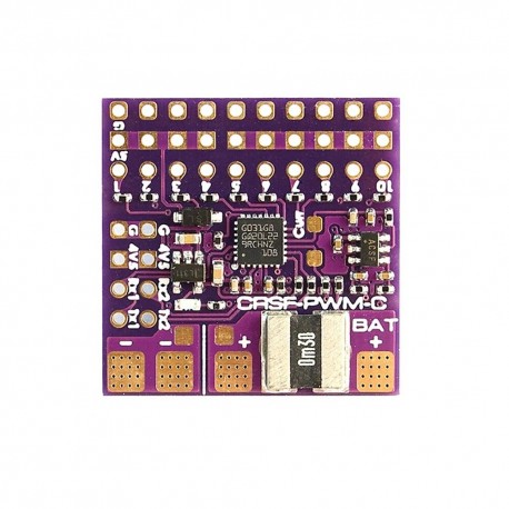 Μεγαλύτερη προβολή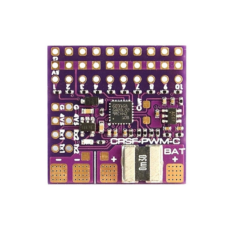
MATEKSYS CRSF-PWM-C CRSF to PWM Converter 10 PWM 50-400Hz Output 2 UARTs Bulit-in Current Sensor Failsaft
(SKU): CRSF-PWM-C
MATEKSYS CRSF-PWM-C CRSF to PWM Converter 10 PWM 50-400Hz Output 2 UARTs Bulit-in Current Sensor Failsaft
Διαθέσιμο
Άλλες πληροφορίες
MATEKSYS CRSF-PWM-C CRSF to PWM Converter 10 PWM 50-400Hz Output 2 UARTs Bulit-in Current Sensor Failsaft Auto Set for RC Receiver
Specifications:
Brand Name: MATEKSYS
Item Name: CRSF-PWM-C Converter
Model: CRSF-PWM-C
Weight: 2.8g
Size: 26x26mm
Compatible with CRSF protocol receiver only
10x PWM outputs
PWM frequency configurable (50Hz default, 100,160,330, 400Hz)
2x UARTs (for Receiver and GPS)
Telemetry ID: RxBt, Curr, Capa, Bat%, GPS, GSpd, Hdg, Alt, Sats
36V Max. battery voltage sense (1K:10K voltage divider built-in)
Current sensor built-in (90A continuous /220A Peak), current scale = 150 by default
Vbat and Current sensor scale configurable
Failsafe value auto set
Firmware upgradeable
Rated voltage: 4~9V @5V pad, 0~36V @BAT+
No 5V regulator built-in
Pinouts and Pads:
Tx1/Rx1(UART1) for CRSF protocol Receiver
Tx2/Rx2(UART2) for GPS/firmware update/setting parameters
1~10: CH1~CH10 PWM outputs
Curr: current sensor signal (0~3.3V)
Vbat: Battery voltage sensing (0~36V)
G: ground
4v5 pad voltage = 5V pad voltage -0.3V, make sure the voltage on 5V pad is not higher than receiver and GPS rated voltage.
Failsafe:
Failsafe value is set automatically after CRSF-PWM board is powered on and receive CRSF signal. LED blinks 8 times quickly.
Failsafe value = The PWM value of each channel(except CH3) when CRSF signal is received by CRSF-PWM board for the first time
CH3 is specially arranged for the throttle, Failsafe value = 988 by default.
Usually put the Throttle joystick to the lowest point, put AIL(Roll), ELE(Pitch), RUD(Yaw) middle before powering on receiver.
LED status:
slow blinks: CRSF-PWM board doesn’t receive CRSF signal, e.g., receiver is not bound with transmitter, receiver is not connected to UART1 of CRSF-PWM board.
8x quick blinks: CRSF-PWM board received CRSF signal and failsafe value is saved.
solid ON: CRSF-PWM board and receiver are working normally
2x slow blinks between 8x fast blink and solid on: CLI mode is active
GPS telemetry:
Compatible with GPS NMEA protocol
GPS “TX” to CRSF-PWM board “RX” Single wire half duplex UART connection, CRSF-PWM board “TX” to GPS “RX” is not essential.
Support GPS Telemetry ID: GPS, GSpd, Hdg, Alt, Sats
u-blox series GPS can output “0+1 – UBX+NMEA” protocol by default
Sensors(GPS, GSpd, Hdg, Alt, Sats) will blink in Transmitter TELEMETRY tab once CRSF-PWM board has connection with GPS.
Troubleshooting for no GPS telemetry, double check the wiring between GPS and CRSF-PWM board, some u-blox GPS may don’t output NMEA protcol, you need to be reverted GPS to default configuration in u-center.
TIM & PWM Frequency:
PWM frequency on all 10x Channels can be configured according to TIM
PWM run at 50Hz by default
TIM2: CH1, CH2, CH4
TIM16: CH3
TIM3: CH5, CH6, CH7, CH8
TIM1: CH9, CH10
CLI mode:
If CRSF-PWM board doesn’t detect GPS connected to UART2 within 10 seconds after powering on, CLI mode will active.
After CLI mode is active, CRSF-PWM board can be connected to configurator via USB-TTL module/FC passthrough.
in CLI mode, CRSF-PWM board firmware can be updated
CLI mode has no effect to receiver CRSF signal and PWM outputs
Package included:
1 x CRSF-PWM-C
1 x low ESR capacitor
1 x Dupont 2.54 pins


