Κανένα προϊόν
ΔΙΑΦΟΡΑ
- DRONES
- ΕΛΙΚΟΠΤΕΡΑ
- ΑΕΡΟΠΛΑΝΑ
- ΑΥΤΟΚΙΝΗΤΑ
- ΣΚΑΦΗ
- ΑΝΤΑΛΛΑΚΤΙΚΑ
- QUAD COPTERS
- MICRO QUAD PARTS
- ALIGN M424 Quadcopter
- Quanum/CX-20/ DJI PARTS
- Cheerson CX-33 Parts
- Cheerson CX-35 parts
- FreeX Parts
- SYMA X5 PARTS
- SYMA X8 PARTS
- HUSBAN PARTS
- WLtoys V686 PARTS
- Tarantula X6
- Q-BOT parts
- Zoopa Q parts
- Eachine
- VISUO XS809/XS816 parts
- Eachine E58 PARTS / X-PRO
- VISUO XS812 GPS parts
- SHRC H1G GPS PARTS
- Eachine Tyro99
- Wltoys XK X1
- FUNSKY S20 PARTS
- Eachine E520S GPS PARTS
- Eachine E511S GPS PARTS
- Eachine Tyro79 parts
- Eachine EG16 parts
- Eachine Tyro129 parts
- Eachine Tyro109 parts
- Eachine Tyro69 parts
- JJRC X16 5G parts
- Eachine Tyro89 parts
- ΕΛΙΚΟΠΤΕΡΑ
- ALIGN
- TREX 100 / TREX 100X
- TREX 150 DFC
- TREX 250 / DFC
- TREX 250SE/PRO/DFC
- TREX 450SE/V1/V2/V3
- TREX 450 SPORT/V2/PLUS
- TREX 450 PRO/V2/DFC/3GX
- 450L DOMINATOR Parts
- TREX 500 /ESP/EFL/PRO/3G/DFC
- TREX 550E / PRO / DFC
- TREX 600E / ESP / 3G / PRO / EFL / DFC
- TREX 600N / Limited / 3G
- TREX 700N / Limited / 700E / 3G / DFC / 800E
- ESKY
- E-FLITE
- TAROT (100% COPY ALIGN)
- WALKERA
- Walkera 38 Parts
- Walkera 4-3B/4-3Q2 Parts
- Walkera 5-10 Parts
- Walkera 5-6 Parts
- Walkera 53-1 Parts
- Walkera 5G6 Parts
- Walkera LAMA2 Parts
- Walkera UFO 5 Parts
- Walkera 4G3 Parts
- Walkera Metal Upgrade Parts
- Walkera 5G6-1 Parts
- Walkera 5G4Q3 Parts
- WALKERA 5-4,5,8 PARTS
- Walkera 53Q3 PARTS
- Walkera UFO8 Parts
- Walkera LAMA 400 Parts
- WALKERA LAMA2Q PARTS
- WALKERA LAMA2Q1 PARTS
- WALKERA UFLY
- Walkera 4G6
- SKYARTEC
- SKYA
- Hisky
- Wltoys
- ARK
- HK
- THUNDER TIGER
- GAUI
- ELE
- OUTRAGE
- COPTER X
- HDX
- Copter V-MAX Parts
- Copter Mini X - SH-6025-1
- ACME HELIS
- XK
- Eachine Parts
- XK-WLTOYS
- RC ERA HELIS
- ALIGN
- ΑΕΡΟΠΛΑΝΑ
- ΑΥΤΟΚΙΝΗΤΑ
- Accessories
- 1/16 Short Course Truck
- 1/16 Brushless 4WD Racing Buggy
- JJRC Q35/Q36 PARTS
- 9115 parts
- Wltoys A989/A999/L939/K969/K989
- WLtoys A949 A959 A969 A979 PARTS
- Wltoys L959/L969/L979
- Wltoys 144001 parts
- Pxtoys PX9300 1/18
- RC Trailer
- Wltoys 12429 parts
- Eachine EAT04/Feiyue FY01/2/3 1/12 parts
- XLF X03 1/10 PARTS
- Xinlehong 913xx 1/16 PARTS
- Wltoys 12428 parts
- Wltoys 104001 1/10 PARTS
- Wltoys 124017 1/12 PARTS
- Wltoys 124018 1/12 PARTS
- HBX 16886 1/14 4WD PARTS
- HBX 903 RTR 1/12 2.4G 4WD PARTS
- HBX 16889A Pro 1/16 2.4G PARTS
- Wltoys 104009/12402 1/10 PARTS
- Wltoys XK 22201 1/22 parts
- F-20 2.4GHz 1/12 - PARTS
- Wltoys 144010 1/14 PARTS
- Eachine EAT15 Parts
- Wltoys 124010 1/12 PARTS
- Wltoys 284131 1/28 PARTS
- Wltoys 284161 1/28 PARTS
- Wltoys 124008 1/12 PARTS
- Wltoys 284010 1/28 PARTS
- 1/10 HSP PARTS
- Wltoys 184008 1/18 - parts
- WLTOYS 144016 1/14 - PARTS
- ΒΑΡΚΕΣ
- ΕΛΙΚΕΣ - BLADES
- RC BEARINGS
- QUAD COPTERS
- ΤΗΛΕΚΑΤΕΥΘΥΝΣΕΙΣ
- ΗΛΕΚΤΡΟΝΙΚΑ
- SPEED CONTROLLERS
- SERVOS
- FPV SYSTEMS
- ΚΑΛΩΔΙΑ & ADAPTERS
- ΕΞΟΜΟΙΩΤΕΣ
- BEC & Regulator
- GADGETS
- ΜΠΟΥΖΟΠΙΠΕΣ
- ΦΩΤΑ & Night Flying
- ACME FlyCams
- ΔΙΑΦΟΡΑ
- ΜΠΑΤΑΡΙΕΣ & ΦΟΡΤΙΣΤΕΣ
- ΜΟΤΕΡ
- ΕΡΓΑΛΕΙΑ & ΑΞΕΣΟΥΑΡ
- ΕΡΓΑΛΕΙΑ ΜΕΤΡΗΣΕΩΝ
- ΒΑΛΙΤΣΕΣ
- COVERING FILMS
- ΚΟΛΛΕΣ & ThreadLock
- ΑΕΡΟΓΡΑΦΟΙ
- ΝΤΙΖΕΣ & AΞΕΣΟΥΑΡ
- ΔΙΑΦΟΡΑ ΑΞΕΣΟΥΑΡ
- ΑΞΕΣΟΥΑΡ NITRO
- ΜΠΟΥΖΙ
- ΜΙΖΕΣ
- ΤΡΟΜΠΕΣ ΚΑΥΣΙΜΟΥ
- ΕΡΓΑΛΕΙΑ & ΔΙΑΦΟΡA Accessories
- ΦΙΛΤΡΑ ΚΑΥΣΙΜΟΥ
- ΒΙΔΕΣ & Washer & E-Clips
- TRAINING KIT
- PITCH GAUGE
- SERVO TESTER
- TAPES & VELCRO
- Lubricants & Accessories
- DECALS & STICKERS
- ΕΡΓΑΛΕΙΑ SKYA
- ΖΥΓΑΡΙΕΣ
- Cleaning Accessories
- Swashplate Leveler
- Starter Shaft
- Glow Ignitors
- ΨΗΦΙΑΚΑ ΠΟΛΥΜΕΤΡΑ
- ΦΩΤΙΣΤΙΚA LED
- ΚΟΛΛΗΤΗΡΙΑ
- ΕΡΓΑΛΕΙΑ ΧΕΙΡΟΣ
- DEPRON
- ΚΟΥΤΙΑ ΑΠΟΘΗΚΕΥΣΗΣ
- ΜΠΡΟΣΕΛΕΣ
- ΔΕΜΑΤΙΚΑ
- ΓΙΑ ΑΡΧΑΡΙΟΥΣ
- GADGETS FOR PC
- ΠΕΡΙΟΔΙΚΑ & DVD
- SLUBAN ΤΟΥΒΛΑΚΙΑ
- 3D PRINTERS / SCANNERS
- 3D PUZZLES
- ARDUINO - ΡΟΜΠΟΤΙΚΗ
- DIY Electronic KIT
 Μεγαλύτερη προβολή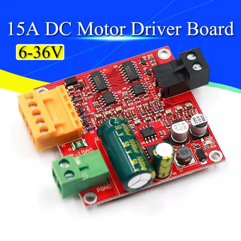
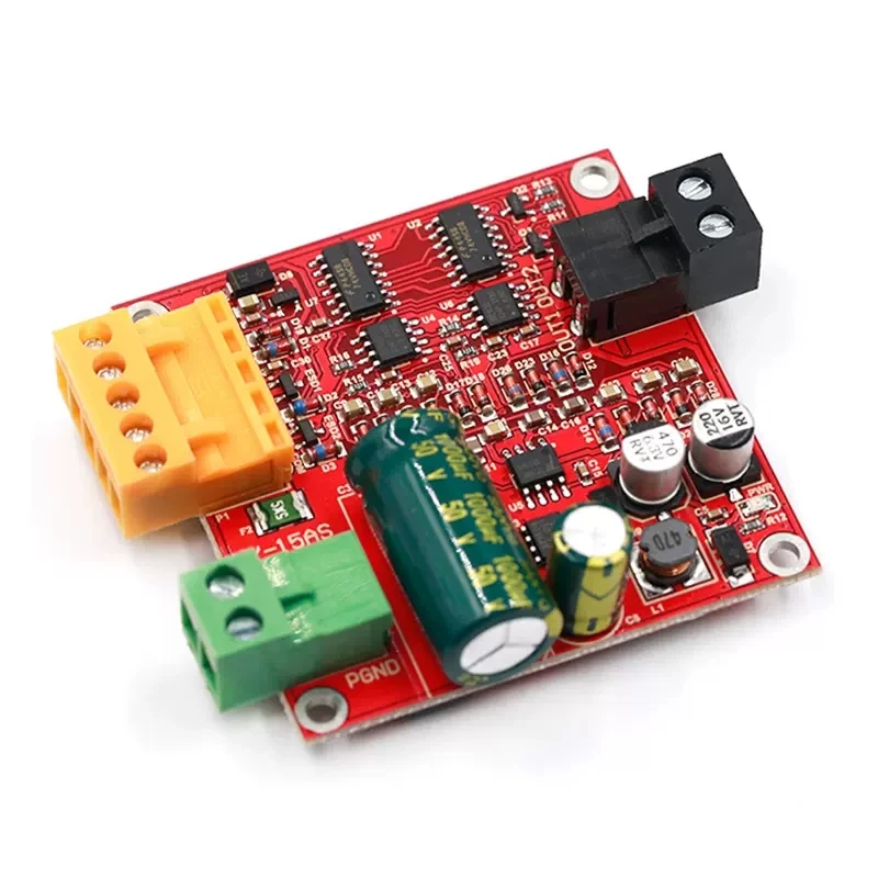
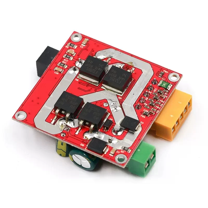
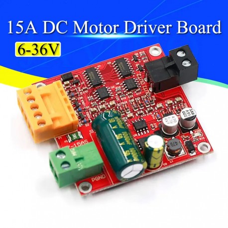
6-36V 15A High Power DC Motor Driver Board Precise DC Motor Drive Plate Module PWM
(SKU): 6-36V/15A-PWM
6-36V 15A High Power DC Motor Driver Board Precise DC Motor Drive Plate Module PWM
Διαθέσιμο
Άλλες πληροφορίες
Product Description
1.Product industrial design,stable and reliable,with anti-static circuit,transient suppression protection,undervoltage protection,interface ESD and over-voltage protection;
2.Support voltage 9-36V wide range,the maximum sustained load current 12A(without heat),15A (simple heat),20A(thick large radiator) ;
3.similar to L 298 drive logic,three lines(PWM,IN 1,IN 2) control speed,forward and reverse and brake;
4.Support full PWM,can be directly used to control the positive and negative keys,PWM effective range of 0.1% to 100.0%;
5.For the microcontroller and other controllers to provide 5V powersupply,and 5V output overcurrent protection,and access signal overvoltage protection.
Control signal logic
Note:0 is low,1 is high,× is any level,floating is low.
COMfort he signal ground,5VO5V output,for the microcontroller and other controllers to provide 5V powersupply; PWM pin external PWM,if the use of key control,PWM pin should be connected with the 5VO; IN1 and IN 2 for the two motor positive and negative turn,brake control signal.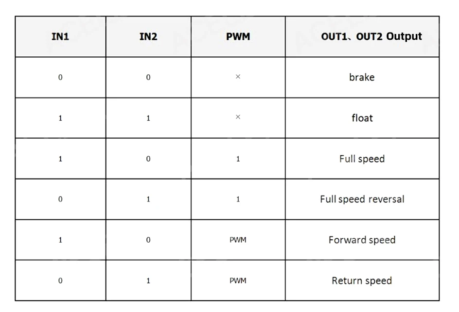 Product Parameter
1.Power supply voltage 6V-36V(voltage is too low,large load current easily lead to damage to the module,so the circuit board labeled 9-36V),the power must not be reversed or more than 37V,or may burn the module,it is recommended that the power Input in series 20Afuse.
2.Drives without heatsink rated current 12A,rated current 12A~15Aneedtodo simple cooling,15A~20A needtodo thick heatsink.(simple cooling-such as in the module below a 1mm thick thermal insulation silicone pad,and then 5mm copper column to the module fixed to the wall) .
3.Control signal interface(orange) can provide users with external 5V,microcontroller no additional power supply,the maximum supply current 0.5A.
4.Controlsignalhighvoltage:2.0V~5.5V,compatible with 3.3V and 5V TTL level;Controlsignallowvoltage:0V~0.8V,0V when floating;When the control signal voltage is 5V,the control signal current is 50 uA.
5.PWMeffectiverange:0.1%~100.0%;PWM signal frequency range:0~100KHz(recommended 20KHz) ;
PWM minimum effective pulse width:200ns.
6.Operating temperature-25℃-80℃.
7.ProductSize:55*55*25mm(lengthandwidth).
8.Mounting hole diameter:3mm.
Motor Parameters
Suitable for motor parameters
(Please do your own according to the motor parameters to do a simple cooling or thick heat treatment) .
1.Rated voltage of 36V motor
The rated power of 300W and below or rated the rated current of 12A the following motor for along time to work without cooling; Logo rated power 300W~370W or rated current 12A~15A motor need todoa simple
heat treatment; Rated rated power 370W~500W or rated rated current 15A~20A motor need to do thick heat treatment;
2.Rated voltage of 24V motor
Marking the rated power of 200W and below or mark the rated current of 12A the following motor for along time to work without cooling; Logo rated power 200W~250W or rated rated current 12A~15A motor need to do a simple heat treatment; Rated rated power 250W~330W or rated rated current 15A~20A motor need to do thick large heat treatment;
3.Rated voltage of 12V motor
Marking the rated power of 70W and below or mark the rated current of 12A the following long motor full work without heat; Logo rated power 70W~90W or rated current 12A~15 Amotor need todoa simple heat treatment; Logo rated power 90W~120W or
rated rated current 15A~20A motor need to do thick heat treatment;
(This drive is not cooling under the conditions of rated current 12A,rated current 12A~15A need to do simple cooling,15A~20Aneed to do thick heat.Motor rated power is generally refers to the output power,consider the motor work loss,so the calculation Rated current to be considered motor efficiency,rated current=rated power/rated voltage/efficiency) .
Wiring Instructions
1.Use the microcontroller to control the motor rotation wiring method Single-chip power supply to connect the drive module COM; PWM pinto the microcontroller's PWM output,for speed,or directly connected to the high-level full speed operation; IN 1,IN 2 and the microcontroller's two lO connected to control the motor is reversing and Brakes; 5VO can provide 5V powersupply for the microcontroller.
2.Use only the keys to control the motor reversing the wiring method PBlandPB2aretwokeys.When the PB1 is pressed and PB2 is not pressed,IN1 is high,IN 2 is low,the motor is turning; when PB2 is pressed and PB1 is not pressed,IN1 is low,IN2 is high,motor reverse; when PB1 and PB2 are bounced,IN1 and IN2 are low,the motor brake.
3.Use OUR PWM generator to the motor speed control wiring method PWMgenerator can be set by the key,select the frequency and duty cycle to control the motor speed; PB1 and PB2 for the two buttons were to control the direction of rotation of the motor,when PB1 and PB 2 are bounced,the motor is braking.
Precautions
1.The drive supply voltage should be between 6-36V. If the power exceeds the rated voltage,it may burn the drive; the voltage is too low,the load current is large,may also cause the drive to burn.It is recommended to connect the 20A fusein series at the power supply.
2.In the forward and reverse switching time is best to brake more than 0.1S and then reverse,otherwise it may damage the drive.
3.Since the control signal line is very fragile,any signal lines(orange terminals) of the control signal can not be routed together with the wiring of the power supply or motor during use.Otherwise,the drive maybe burned and difficult to be repaired.
4.When the drive is powered down,do not turn the motor quickly,or the motor's electromotive force may burn the drive.If the application requires the drive to power down when the machine should also quickly turn the motor,it is recommended in the drive motor interface string of a relay,relay coil and drive power supply.In this way,when the power supply is turned off,the relay disconnects the drive from the motor.
5.The drive should be connected to the motor before it is powered on,otherwise it may burn the fuse or drive.
6.Motor interface must not be short-circuited,otherwise it may burn the fuse or drive.
7.Note that the drive does not get wet,do not let the components on the drive boardshort circuit,do not touch the components on the board pins and pads.
8.Please carefully read the product before use,if your error caused the module damage,or you have unauthorized replacement of the module device,no refund.
Package included:
1*6-36V 15A High Power DC Motor Driver Board