Κανένα προϊόν
VIDEO TX/RX
- DRONES
- ΕΛΙΚΟΠΤΕΡΑ
- ΑΕΡΟΠΛΑΝΑ
- ΑΥΤΟΚΙΝΗΤΑ
- ΣΚΑΦΗ
- ΑΝΤΑΛΛΑΚΤΙΚΑ
- QUAD COPTERS
- MICRO QUAD PARTS
- ALIGN M424 Quadcopter
- Quanum/CX-20/ DJI PARTS
- Cheerson CX-33 Parts
- Cheerson CX-35 parts
- FreeX Parts
- SYMA X5 PARTS
- SYMA X8 PARTS
- HUSBAN PARTS
- WLtoys V686 PARTS
- Tarantula X6
- Q-BOT parts
- Zoopa Q parts
- Eachine
- VISUO XS809/XS816 parts
- Eachine E58 PARTS / X-PRO
- VISUO XS812 GPS parts
- SHRC H1G GPS PARTS
- Eachine Tyro99
- Wltoys XK X1
- FUNSKY S20 PARTS
- Eachine E520S GPS PARTS
- Eachine E511S GPS PARTS
- Eachine Tyro79 parts
- Eachine EG16 parts
- Eachine Tyro129 parts
- Eachine Tyro109 parts
- Eachine Tyro69 parts
- JJRC X16 5G parts
- Eachine Tyro89 parts
- ΕΛΙΚΟΠΤΕΡΑ
- ALIGN
- TREX 100 / TREX 100X
- TREX 150 DFC
- TREX 250 / DFC
- TREX 250SE/PRO/DFC
- TREX 450SE/V1/V2/V3
- TREX 450 SPORT/V2/PLUS
- TREX 450 PRO/V2/DFC/3GX
- 450L DOMINATOR Parts
- TREX 500 /ESP/EFL/PRO/3G/DFC
- TREX 550E / PRO / DFC
- TREX 600E / ESP / 3G / PRO / EFL / DFC
- TREX 600N / Limited / 3G
- TREX 700N / Limited / 700E / 3G / DFC / 800E
- ESKY
- E-FLITE
- TAROT (100% COPY ALIGN)
- WALKERA
- Walkera 38 Parts
- Walkera 4-3B/4-3Q2 Parts
- Walkera 5-10 Parts
- Walkera 5-6 Parts
- Walkera 53-1 Parts
- Walkera 5G6 Parts
- Walkera LAMA2 Parts
- Walkera UFO 5 Parts
- Walkera 4G3 Parts
- Walkera Metal Upgrade Parts
- Walkera 5G6-1 Parts
- Walkera 5G4Q3 Parts
- WALKERA 5-4,5,8 PARTS
- Walkera 53Q3 PARTS
- Walkera UFO8 Parts
- Walkera LAMA 400 Parts
- WALKERA LAMA2Q PARTS
- WALKERA LAMA2Q1 PARTS
- WALKERA UFLY
- Walkera 4G6
- SKYARTEC
- SKYA
- Hisky
- Wltoys
- ARK
- HK
- THUNDER TIGER
- GAUI
- ELE
- OUTRAGE
- COPTER X
- HDX
- Copter V-MAX Parts
- Copter Mini X - SH-6025-1
- ACME HELIS
- XK
- Eachine Parts
- XK-WLTOYS
- RC ERA HELIS
- ALIGN
- ΑΕΡΟΠΛΑΝΑ
- ΑΥΤΟΚΙΝΗΤΑ
- Accessories
- 1/16 Short Course Truck
- 1/16 Brushless 4WD Racing Buggy
- JJRC Q35/Q36 PARTS
- 9115 parts
- Wltoys A989/A999/L939/K969/K989
- WLtoys A949 A959 A969 A979 PARTS
- Wltoys L959/L969/L979
- Wltoys 144001 parts
- Pxtoys PX9300 1/18
- RC Trailer
- Wltoys 12429 parts
- Eachine EAT04/Feiyue FY01/2/3 1/12 parts
- XLF X03 1/10 PARTS
- Xinlehong 913xx 1/16 PARTS
- Wltoys 12428 parts
- Wltoys 104001 1/10 PARTS
- Wltoys 124017 1/12 PARTS
- Wltoys 124018 1/12 PARTS
- HBX 16886 1/14 4WD PARTS
- HBX 903 RTR 1/12 2.4G 4WD PARTS
- HBX 16889A Pro 1/16 2.4G PARTS
- Wltoys 104009/12402 1/10 PARTS
- Wltoys XK 22201 1/22 parts
- F-20 2.4GHz 1/12 - PARTS
- Wltoys 144010 1/14 PARTS
- Eachine EAT15 Parts
- Wltoys 124010 1/12 PARTS
- Wltoys 284131 1/28 PARTS
- Wltoys 284161 1/28 PARTS
- Wltoys 124008 1/12 PARTS
- Wltoys 284010 1/28 PARTS
- 1/10 HSP PARTS
- Wltoys 184008 1/18 - parts
- WLTOYS 144016 1/14 - PARTS
- ΒΑΡΚΕΣ
- ΕΛΙΚΕΣ - BLADES
- RC BEARINGS
- QUAD COPTERS
- ΤΗΛΕΚΑΤΕΥΘΥΝΣΕΙΣ
- ΗΛΕΚΤΡΟΝΙΚΑ
- SPEED CONTROLLERS
- SERVOS
- FPV SYSTEMS
- ΚΑΛΩΔΙΑ & ADAPTERS
- ΕΞΟΜΟΙΩΤΕΣ
- BEC & Regulator
- GADGETS
- ΜΠΟΥΖΟΠΙΠΕΣ
- ΦΩΤΑ & Night Flying
- ACME FlyCams
- ΔΙΑΦΟΡΑ
- ΜΠΑΤΑΡΙΕΣ & ΦΟΡΤΙΣΤΕΣ
- ΜΟΤΕΡ
- ΕΡΓΑΛΕΙΑ & ΑΞΕΣΟΥΑΡ
- ΕΡΓΑΛΕΙΑ ΜΕΤΡΗΣΕΩΝ
- ΒΑΛΙΤΣΕΣ
- COVERING FILMS
- ΚΟΛΛΕΣ & ThreadLock
- ΑΕΡΟΓΡΑΦΟΙ
- ΝΤΙΖΕΣ & AΞΕΣΟΥΑΡ
- ΔΙΑΦΟΡΑ ΑΞΕΣΟΥΑΡ
- ΑΞΕΣΟΥΑΡ NITRO
- ΜΠΟΥΖΙ
- ΜΙΖΕΣ
- ΤΡΟΜΠΕΣ ΚΑΥΣΙΜΟΥ
- ΕΡΓΑΛΕΙΑ & ΔΙΑΦΟΡA Accessories
- ΦΙΛΤΡΑ ΚΑΥΣΙΜΟΥ
- ΒΙΔΕΣ & Washer & E-Clips
- TRAINING KIT
- PITCH GAUGE
- SERVO TESTER
- TAPES & VELCRO
- Lubricants & Accessories
- DECALS & STICKERS
- ΕΡΓΑΛΕΙΑ SKYA
- ΖΥΓΑΡΙΕΣ
- Cleaning Accessories
- Swashplate Leveler
- Starter Shaft
- Glow Ignitors
- ΨΗΦΙΑΚΑ ΠΟΛΥΜΕΤΡΑ
- ΦΩΤΙΣΤΙΚA LED
- ΚΟΛΛΗΤΗΡΙΑ
- ΕΡΓΑΛΕΙΑ ΧΕΙΡΟΣ
- DEPRON
- ΚΟΥΤΙΑ ΑΠΟΘΗΚΕΥΣΗΣ
- ΜΠΡΟΣΕΛΕΣ
- ΔΕΜΑΤΙΚΑ
- ΓΙΑ ΑΡΧΑΡΙΟΥΣ
- GADGETS FOR PC
- ΠΕΡΙΟΔΙΚΑ & DVD
- SLUBAN ΤΟΥΒΛΑΚΙΑ
- 3D PRINTERS / SCANNERS
- 3D PUZZLES
- ARDUINO - ΡΟΜΠΟΤΙΚΗ
- DIY Electronic KIT
 Μεγαλύτερη προβολή
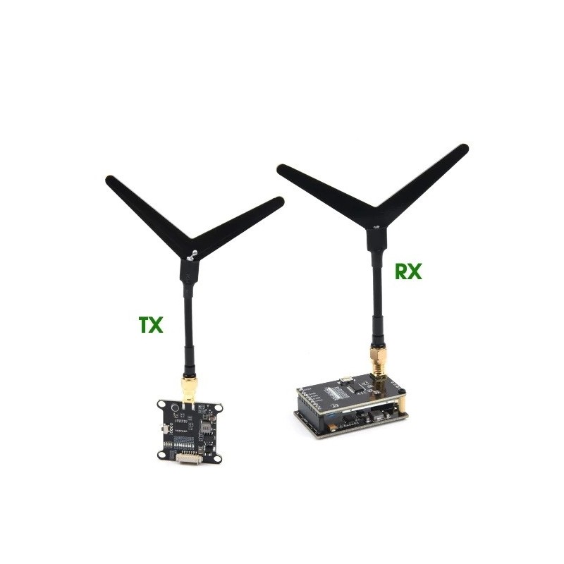
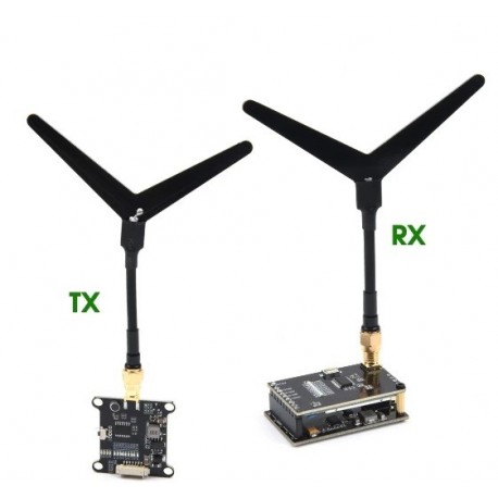
FPV 1.2GHz 0.1mW/25mW/200mW/800mW 9CH Transmitter VTX & Receiver VRX FPV Combo for RC Drone Airplane Long Range
(SKU): K38854
FPV 1.2GHz 0.1mW/25mW/200mW/800mW 9CH Transmitter VTX & Receiver VRX FPV Combo for RC Drone Airplane Long Range
Διαθέσιμο
Άλλες πληροφορίες
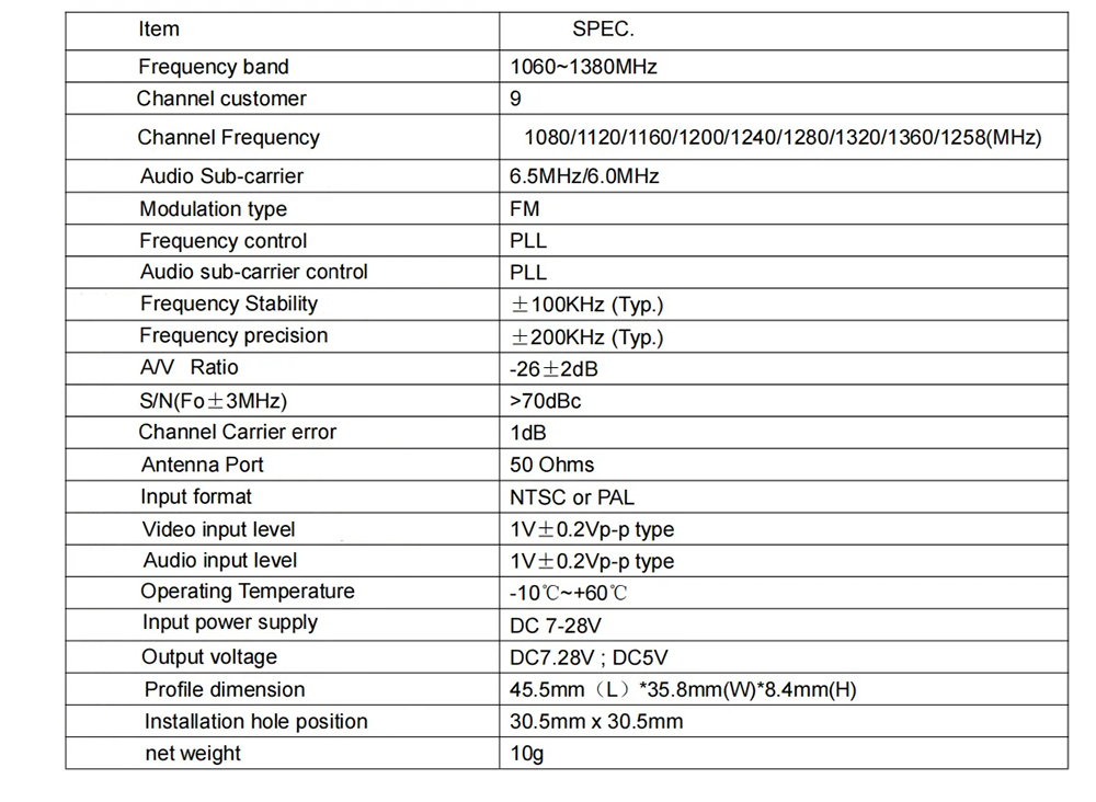
Transmitter:
Button control and LED indicators
Green indicator 4pcs are power indicators: 0.1mW(0)/25mW(D)/200mW(C)/800mW(H).
The default is 0.1mW when the power is on. To the next power level. This operation can be cycled and the corresponding power indicator will light up every time you press and hold the button.The corresponding power indicator will light up each time you press and hold the button.
Note: The transmitting power must be readjusted after each power failure.
The 9 red LEDs are frequency indicators.
This operation can be cycled, each short press on the corresponding frequency point indicator will light up.
Note: The operating system has a memory function, the system will save the current frequency point after power failure.
Interface definition:
The antenna is SMA interface, the antenna head is "male thread + hole" and the antenna pole is "female thread + pin".
Pin" configuration 1.2G special customized "Y" type antenna.
The order of the socket connection is:
1. power input DC 7-28V;
2. input ground;
3. video input;
4. 6.5M audio input;
5. DC output 7-28V;
6. DC output ground;
7. DC output 5V.
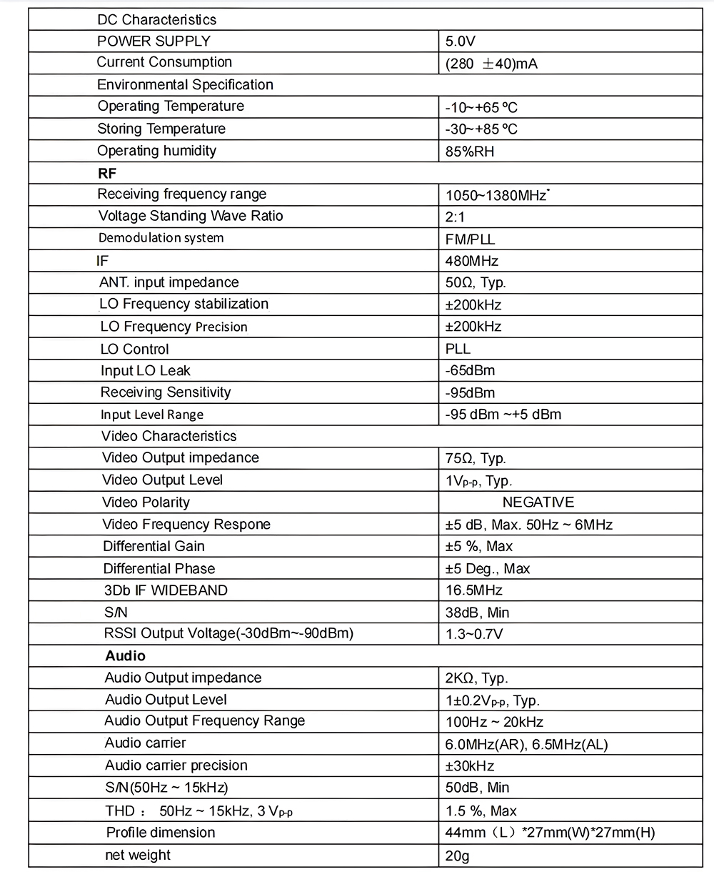
Receiver:
Button control and LED indicators
The 9 red indicators are the frequency point indicators and are switched to the next frequency point by pressing the button once.
This operation can be cycled, each short press of the corresponding frequency point indicator will light up.
Note: This operating system has a memory function, the system will save the current frequency point after a power failure.
Interface definition:
The antenna is SMA interface; the antenna head is "male thread + hole" and the antenna pole is "female thread + pin".
Pin" configuration 1.2G special customized "Y" type antenna.
The order of the socket connections is:
1. power input DC 7-28V;
2. input ground;
3. video input;
4. 6.5M audio input;
5. DC output 7-28V;
6. DC output ground;
7. DC output 5V.
Reserved 5P pads are defined in the following order:
1. power input DC 7-28V;
2. input ground;
3. video input;
4. DC output 5V;
5. DC output ground.