Cart 0 Product Products (empty)
No products
To be determined Shipping
0,00 € Total
Product successfully added to your shopping cart
Quantity
Total
There are 0 items in your cart. There is 1 item in your cart.
Total products
Total shipping To be determined
Total
ΔΙΑΦΟΡΑ
- DRONES
- HELIS
- PLANES
- CARS
- BOATS
- SPARE PARTS
- QUAD COPTERS
- MICRO QUAD PARTS
- ALIGN M424 Quadcopter
- Quanum/CX-20/ DJI PARTS
- Cheerson CX-33 Parts
- Cheerson CX-35 parts
- freeX Parts
- SYMA X5 PARTS
- SYMA X8 PARTS
- HUSBAN PARTS
- WLtoys PARTS
- Tarantula X6
- Q-BOT PARTS
- Zoopa Q parts
- Eachine
- VISUO XS809/XS816 parts
- Eachine E58 PARTS / X-PRO
- VISUO XS812 GPS parts
- SHRC H1G GPS PARTS
- Eachine Tyro99
- Wltoys XK X1
- FUNSKY S20 PARTS
- Eachine E520S GPS PARTS
- Eachine E511S GPS PARTS
- Eachine Tyro79 parts
- Eachine EG16 parts
- Eachine Tyro129 parts
- Eachine Tyro109 parts
- Eachine Tyro69 parts
- JJRC X16 5G parts
- Eachine Tyro89 parts
- ΕΛΙΚΟΠΤΕΡΑ
- ALIGN
- ESKY
- E-FLITE
- TAROT (100% COPY ALIGN)
- WALKERA
- Walkera 38 Parts
- Walkera 4-3B/4-3Q2 Parts
- Walkera 5-10 Parts
- Walkera 5-6 Parts
- Walkera 53-1 Parts
- Walkera 5G6 Parts
- Walkera LAMA2 Parts
- Walkera UFO 5 Parts
- Walkera 4G3 Parts
- Walkera Metal Upgrade Parts
- Walkera 5G6-1 Parts
- Walkera 5G4Q3 Parts
- WALKERA 5-4,5,8 PARTS
- Walkera 53Q3 PARTS
- Walkera UFO8 Parts
- Walkera LAMA 400 Parts
- WALKERA LAMA2Q PARTS
- WALKERA LAMA2Q1 PARTS
- WALKERA UFLY
- Walkera 4G6
- SKYARTEC
- SKYA
- Hisky
- Wltoys
- ARK
- HK
- THUNDER TIGER
- GAUI
- ELE
- OUTRAGE
- COPTER X
- HDX
- Copter V-MAX Parts
- Copter Mini X - SH-6025-1
- ACME HELIS
- XK
- Eachine Parts
- XK-WLTOYS
- RC ERA HELIS
- ΑΕΡΟΠΛΑΝΑ
- ΑΥΤΟΚΙΝΗΤΑ
- Accessories
- 1/16 Short Course Truck
- 1/16 Brushless 4WD Racing Buggy
- JJRC Q35/Q36 PARTS
- 9115 parts
- Wltoys A989/A999/L939/K969/K989
- WLtoys A949 A959 A969 A979 PARTS
- Wltoys L959/L969/L979
- Wltoys 144001 parts
- Pxtoys PX9300 1/18
- RC Trailer
- Wltoys 12429 parts
- Eachine EAT04/Feiyue FY01/2/3 1/12 parts
- XLF X03 1/10 PARTS
- Xinlehong 913xx 1/16 PARTS
- Wltoys 12428 parts
- Wltoys 104001 1/10 PARTS
- Wltoys 124017 1/12 PARTS
- Wltoys 124018 1/12 PARTS
- HBX 16886 1/14 4WD PARTS
- HBX 903 RTR 1/12 2.4G 4WD PARTS
- HBX 16889A Pro 1/16 2.4G PARTS
- Wltoys 104009/12402 1/10 PARTS
- Wltoys XK 22201 1/22 parts
- F-20 2.4GHz 1/12 - PARTS
- Wltoys 144010 1/14 PARTS
- Eachine EAT15 Parts
- Wltoys 124010 1/12 PARTS
- Wltoys 284131 1/28 PARTS
- Wltoys 284161 1/28 PARTS
- Wltoys 124008 1/12 PARTS
- Wltoys 284010 1/28 PARTS
- 1/10 HSP PARTS
- Wltoys 184008 1/18 - parts
- WLTOYS 144016 1/14 - PARTS
- BOATS
- BLADES
- RC BEARINGS
- QUAD COPTERS
- RADIOS
- ELECTRONICS
- SPEED CONTROLLERS
- SERVOS
- FPV SYSTEMS
- ΚΑΛΩΔΙΑ & ADAPTERS
- SIMULATORS
- BEC & Regulator
- GADGETS
- ΜΠΟΥΖΟΠΙΠΕΣ
- ΦΩΤΑ & Night Flying
- ACME FlyCams
- ΔΙΑΦΟΡΑ
- BATTERIES & CHARGERS
- MOTOR
- TOOLS-ACCESSORIES
- ΕΡΓΑΛΕΙΑ ΜΕΤΡΗΣΕΩΝ
- ΒΑΛΙΤΣΕΣ
- COVERING FILMS
- ΚΟΛΛΕΣ & ThreadLock
- ΑΕΡΟΓΡΑΦΟΙ
- ΝΤΙΖΕΣ & AΞΕΣΟΥΑΡ
- ΔΙΑΦΟΡΑ ΑΞΕΣΟΥΑΡ
- ΑΞΕΣΟΥΑΡ NITRO
- ΜΠΟΥΖΙ
- ΜΙΖΕΣ
- ΤΡΟΜΠΕΣ ΚΑΥΣΙΜΟΥ
- ΕΡΓΑΛΕΙΑ & ΟΡΓΑΝΑ ΑΚΡΙΒΕΙΑΣ
- ΦΙΛΤΡΑ ΚΑΥΣΙΜΟΥ
- ΒΙΔΕΣ & Washer & E-Clips
- TRAINING KIT
- PITCH GAUGE
- TESTER
- TAPES & VELCRO
- Lubricants & Accessories
- DECALS & STICKERS
- ΕΡΓΑΛΕΙΑ MULTIFUNCTIONAL SKYA
- ΖΥΓΑΡΙΕΣ
- Cleaning Accessories
- Swashplate Leveler
- Starter Shaft
- Glow Ignitors
- DIGITAL MULTIMETERS
- LIGHTNING LED
- SOLDERING IRON
- HAND TOOLS
- DEPRON
- ΚΟΥΤΙΑ ΑΠΟΘΗΚΕΥΣΗΣ
- ΜΠΡΟΣΕΛΕΣ
- ΔΕΜΑΤΙΚΑ
- FOR BEGINNERS
- GADGETS FOR PC
- MAGAZINES & DVD
- SLUBAN BRICKS
- 3D PRINTERS / SCANNERS
- 3D PUZZLES
- ARDUINO - ROBOTICS
- DIY Electronic KIT


PWM to Voltage Converter Frequency Voltage Converter Board Module 0-10KHz to 0-10V 0-10V to 0-10KHz
PWM to Voltage Converter Frequency Voltage Converter Board Module 0-10KHz to 0-10V 0-10V to 0-10KHz
In stock
More info
Product introduction:
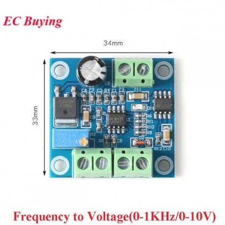
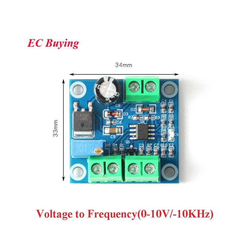
This module is a frequency conversion pulse signal and voltage conversion module. The voltage-to-frequency pulse signal can generate different frequency modules according to the input voltage level. The frequency to analog voltage signal can convert 0-1KHZ frequency to 0-10V voltage output, and adjust the frequency to change the output voltage.
Product parameter:
Frequency to voltage module:
Working voltage: 13.5V-30V
Input frequency range: 0-1KHz
Output voltage range: 0-10V
Output voltage: adjustable (calibrate the relationship between frequency and voltage through a potentiometer)
Precautions:
Input different frequencies and output corresponding voltages.
The input pulse level is 5V, 12V, 24V and can be directly input without series resistance. But the input signal frequency should be maintained for more than 0.5 seconds
The output voltage can be fine-tuned. The relationship between frequency and voltage can be calibrated by a potentiometer.
The signal input terminal uses optical coupling isolation to ensure anti-interference ability.
If need to match PLC, support NPN type. There must be a ground wire.
If it needs to be equipped with an encoder, the encoder must be rotated at a constant speed for more than 0.5 seconds.
F/V conversion module, response time is about 0.3-0.5 seconds. If the frequency is adjusted at one time, a certain response time is required.
Voltage to frequency module:
Working voltage: 13.5V-30V
Input controllable voltage range: 0-10V
Output frequency range: 0-10KHZ
Precautions:
Input voltage, output frequency signal
The output signal can be fine-tuned, and the potentiometer can be adjusted to calibrate the correspondence between voltage and frequency. The output of this module can be supplied to the driver as a pulse signal. When used with the driver, the common anode wiring is used. The related wiring is OC-OUT, which is connected to the driver's PUL- or PUL. 12-30, connected to the drive PUL+ or public terminal +5V, (a 330R resistor is required for 12V power supply, a 2.7K resistor is required for 13-24V power supply for current limiting)
Pin description:
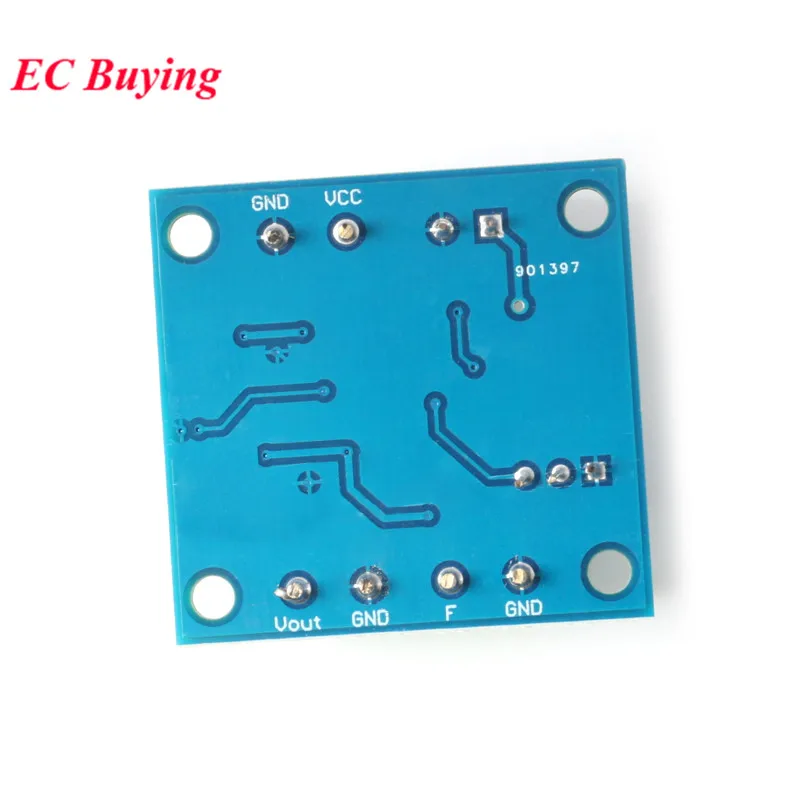
Frequency to voltage module:
VCC: working power supply.
GND: power ground.
F: Input frequency pulse signal.
GND: Input ground.
Vout: output corresponding voltage.
GND: output ground.
The modules share a common ground.
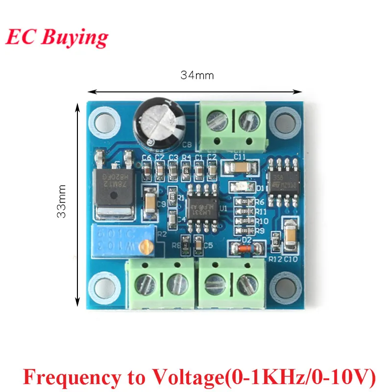
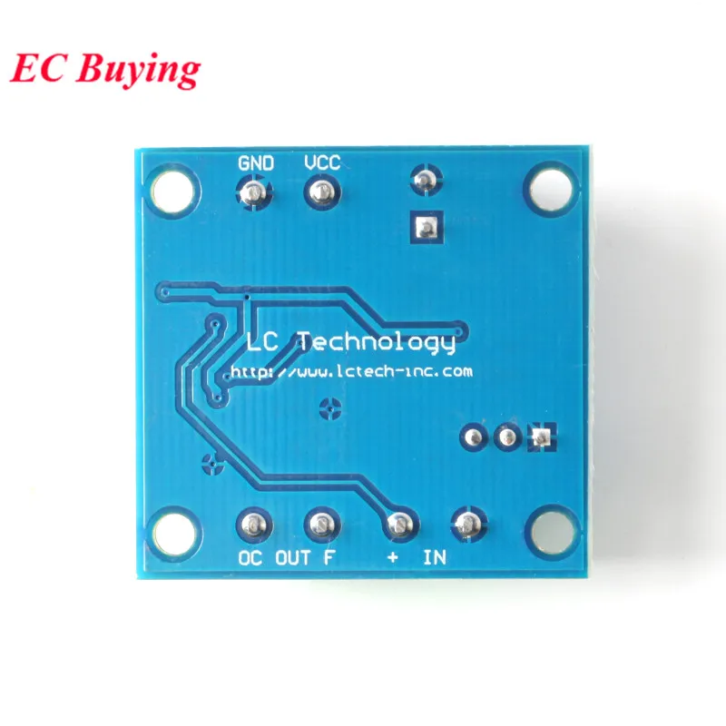
Voltage to frequency module:
VCC: working power supply.
GND: Power ground.
IN+: positive input voltage
IN-: input voltage negative
OCOUT: signal collector output port (use this output port when equipped with driver)
FOUT: frequency output port (general frequency output port)