Κανένα προϊόν
Electronics
- DRONES
- ΕΛΙΚΟΠΤΕΡΑ
- ΑΕΡΟΠΛΑΝΑ
- ΑΥΤΟΚΙΝΗΤΑ
- ΣΚΑΦΗ
- ΑΝΤΑΛΛΑΚΤΙΚΑ
- QUAD COPTERS
- MICRO QUAD PARTS
- ALIGN M424 Quadcopter
- Quanum/CX-20/ DJI PARTS
- Cheerson CX-33 Parts
- Cheerson CX-35 parts
- FreeX Parts
- SYMA X5 PARTS
- SYMA X8 PARTS
- HUSBAN PARTS
- WLtoys V686 PARTS
- Tarantula X6
- Q-BOT parts
- Zoopa Q parts
- Eachine
- VISUO XS809/XS816 parts
- Eachine E58 PARTS / X-PRO
- VISUO XS812 GPS parts
- SHRC H1G GPS PARTS
- Eachine Tyro99
- Wltoys XK X1
- FUNSKY S20 PARTS
- Eachine E520S GPS PARTS
- Eachine E511S GPS PARTS
- Eachine Tyro79 parts
- Eachine EG16 parts
- Eachine Tyro129 parts
- Eachine Tyro109 parts
- Eachine Tyro69 parts
- JJRC X16 5G parts
- Eachine Tyro89 parts
- ΕΛΙΚΟΠΤΕΡΑ
- ALIGN
- TREX 100 / TREX 100X
- TREX 150 DFC
- TREX 250 / DFC
- TREX 250SE/PRO/DFC
- TREX 450SE/V1/V2/V3
- TREX 450 SPORT/V2/PLUS
- TREX 450 PRO/V2/DFC/3GX
- 450L DOMINATOR Parts
- TREX 500 /ESP/EFL/PRO/3G/DFC
- TREX 550E / PRO / DFC
- TREX 600E / ESP / 3G / PRO / EFL / DFC
- TREX 600N / Limited / 3G
- TREX 700N / Limited / 700E / 3G / DFC / 800E
- ESKY
- E-FLITE
- TAROT (100% COPY ALIGN)
- WALKERA
- Walkera 38 Parts
- Walkera 4-3B/4-3Q2 Parts
- Walkera 5-10 Parts
- Walkera 5-6 Parts
- Walkera 53-1 Parts
- Walkera 5G6 Parts
- Walkera LAMA2 Parts
- Walkera UFO 5 Parts
- Walkera 4G3 Parts
- Walkera Metal Upgrade Parts
- Walkera 5G6-1 Parts
- Walkera 5G4Q3 Parts
- WALKERA 5-4,5,8 PARTS
- Walkera 53Q3 PARTS
- Walkera UFO8 Parts
- Walkera LAMA 400 Parts
- WALKERA LAMA2Q PARTS
- WALKERA LAMA2Q1 PARTS
- WALKERA UFLY
- Walkera 4G6
- SKYARTEC
- SKYA
- Hisky
- Wltoys
- ARK
- HK
- THUNDER TIGER
- GAUI
- ELE
- OUTRAGE
- COPTER X
- HDX
- Copter V-MAX Parts
- Copter Mini X - SH-6025-1
- ACME HELIS
- XK
- Eachine Parts
- XK-WLTOYS
- RC ERA HELIS
- ALIGN
- ΑΕΡΟΠΛΑΝΑ
- ΑΥΤΟΚΙΝΗΤΑ
- Accessories
- 1/16 Short Course Truck
- 1/16 Brushless 4WD Racing Buggy
- JJRC Q35/Q36 PARTS
- 9115 parts
- Wltoys A989/A999/L939/K969/K989
- WLtoys A949 A959 A969 A979 PARTS
- Wltoys L959/L969/L979
- Wltoys 144001 parts
- Pxtoys PX9300 1/18
- RC Trailer
- Wltoys 12429 parts
- Eachine EAT04/Feiyue FY01/2/3 1/12 parts
- XLF X03 1/10 PARTS
- Xinlehong 913xx 1/16 PARTS
- Wltoys 12428 parts
- Wltoys 104001 1/10 PARTS
- Wltoys 124017 1/12 PARTS
- Wltoys 124018 1/12 PARTS
- HBX 16886 1/14 4WD PARTS
- HBX 903 RTR 1/12 2.4G 4WD PARTS
- HBX 16889A Pro 1/16 2.4G PARTS
- Wltoys 104009/12402 1/10 PARTS
- Wltoys XK 22201 1/22 parts
- F-20 2.4GHz 1/12 - PARTS
- Wltoys 144010 1/14 PARTS
- Eachine EAT15 Parts
- Wltoys 124010 1/12 PARTS
- Wltoys 284131 1/28 PARTS
- Wltoys 284161 1/28 PARTS
- Wltoys 124008 1/12 PARTS
- Wltoys 284010 1/28 PARTS
- 1/10 HSP PARTS
- Wltoys 184008 1/18 - parts
- WLTOYS 144016 1/14 - PARTS
- ΒΑΡΚΕΣ
- ΕΛΙΚΕΣ - BLADES
- RC BEARINGS
- QUAD COPTERS
- ΤΗΛΕΚΑΤΕΥΘΥΝΣΕΙΣ
- ΗΛΕΚΤΡΟΝΙΚΑ
- SPEED CONTROLLERS
- SERVOS
- FPV SYSTEMS
- ΚΑΛΩΔΙΑ & ADAPTERS
- ΕΞΟΜΟΙΩΤΕΣ
- BEC & Regulator
- GADGETS
- ΜΠΟΥΖΟΠΙΠΕΣ
- ΦΩΤΑ & Night Flying
- ACME FlyCams
- ΔΙΑΦΟΡΑ
- ΜΠΑΤΑΡΙΕΣ & ΦΟΡΤΙΣΤΕΣ
- ΜΟΤΕΡ
- ΕΡΓΑΛΕΙΑ & ΑΞΕΣΟΥΑΡ
- ΕΡΓΑΛΕΙΑ ΜΕΤΡΗΣΕΩΝ
- ΒΑΛΙΤΣΕΣ
- COVERING FILMS
- ΚΟΛΛΕΣ & ThreadLock
- ΑΕΡΟΓΡΑΦΟΙ
- ΝΤΙΖΕΣ & AΞΕΣΟΥΑΡ
- ΔΙΑΦΟΡΑ ΑΞΕΣΟΥΑΡ
- ΑΞΕΣΟΥΑΡ NITRO
- ΜΠΟΥΖΙ
- ΜΙΖΕΣ
- ΤΡΟΜΠΕΣ ΚΑΥΣΙΜΟΥ
- ΕΡΓΑΛΕΙΑ & ΔΙΑΦΟΡA Accessories
- ΦΙΛΤΡΑ ΚΑΥΣΙΜΟΥ
- ΒΙΔΕΣ & Washer & E-Clips
- TRAINING KIT
- PITCH GAUGE
- SERVO TESTER
- TAPES & VELCRO
- Lubricants & Accessories
- DECALS & STICKERS
- ΕΡΓΑΛΕΙΑ SKYA
- ΖΥΓΑΡΙΕΣ
- Cleaning Accessories
- Swashplate Leveler
- Starter Shaft
- Glow Ignitors
- ΨΗΦΙΑΚΑ ΠΟΛΥΜΕΤΡΑ
- ΦΩΤΙΣΤΙΚA LED
- ΚΟΛΛΗΤΗΡΙΑ
- ΕΡΓΑΛΕΙΑ ΧΕΙΡΟΣ
- DEPRON
- ΚΟΥΤΙΑ ΑΠΟΘΗΚΕΥΣΗΣ
- ΜΠΡΟΣΕΛΕΣ
- ΔΕΜΑΤΙΚΑ
- ΓΙΑ ΑΡΧΑΡΙΟΥΣ
- GADGETS FOR PC
- ΠΕΡΙΟΔΙΚΑ & DVD
- SLUBAN ΤΟΥΒΛΑΚΙΑ
- 3D PRINTERS / SCANNERS
- 3D PUZZLES
- ARDUINO - ΡΟΜΠΟΤΙΚΗ
- DIY Electronic KIT
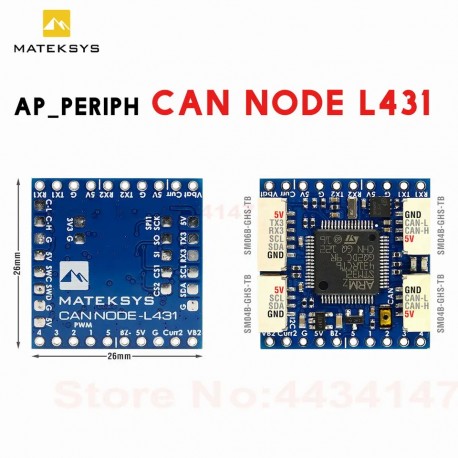
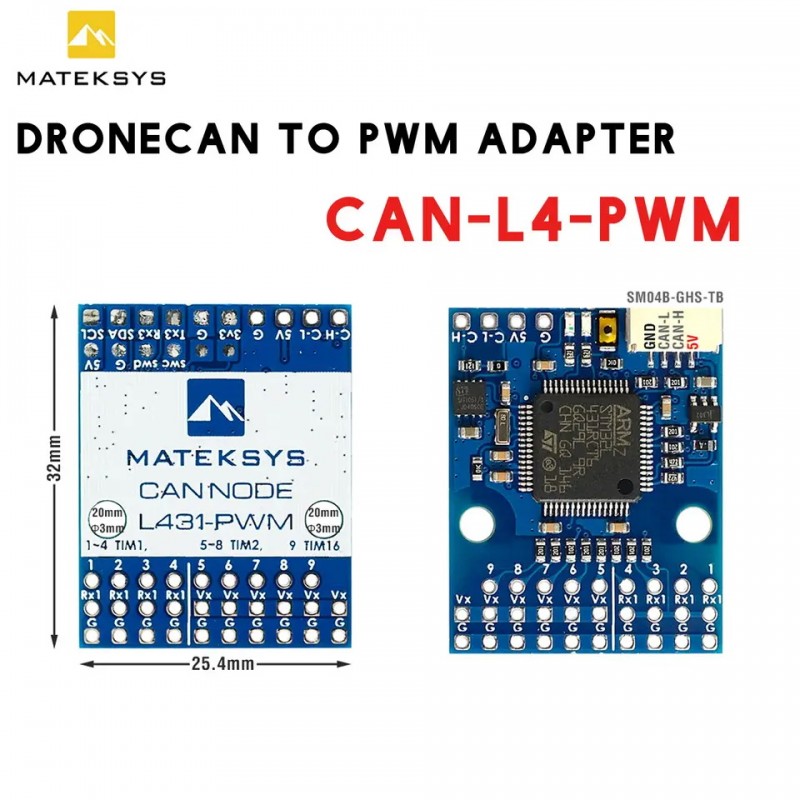
MATEK CAN-L4-PWM / L431 AP_PERIPH DRONECAN TO PWM ADAPTER ArudPilot Turn PWM Servos Into CAN DShot Capable ESCs
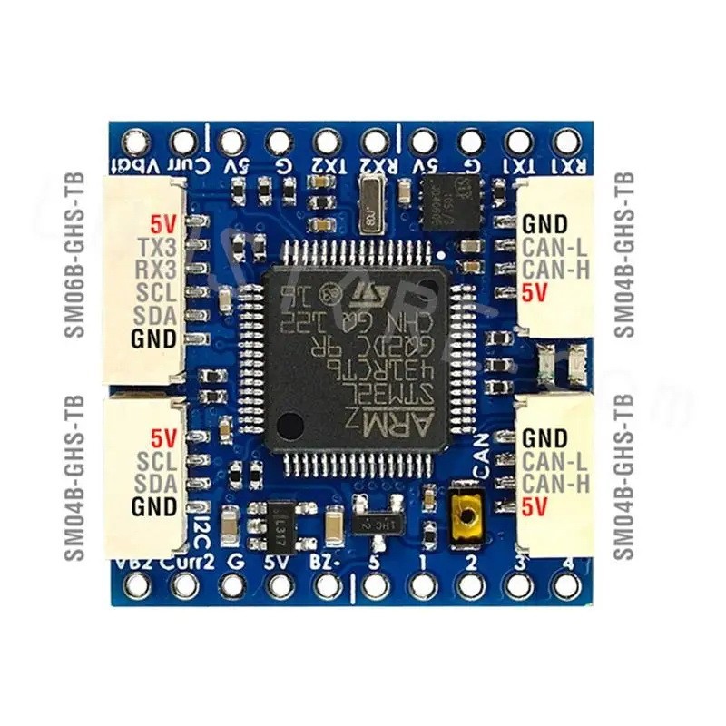
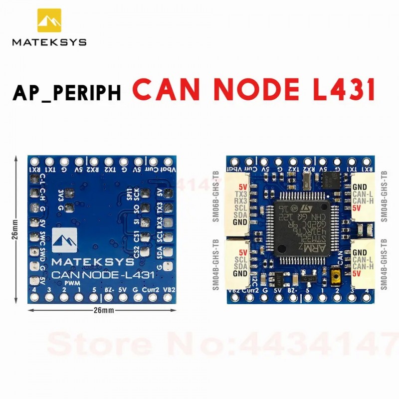
MATEK CAN-L431 AP_Periph CAN Node DroneCAN L431 26X26mm for ArduPilot
Διαθέσιμο
Άλλες πληροφορίες
CAN-L4-PWM
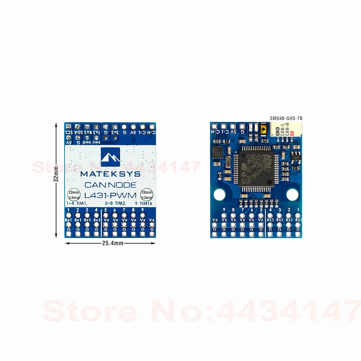
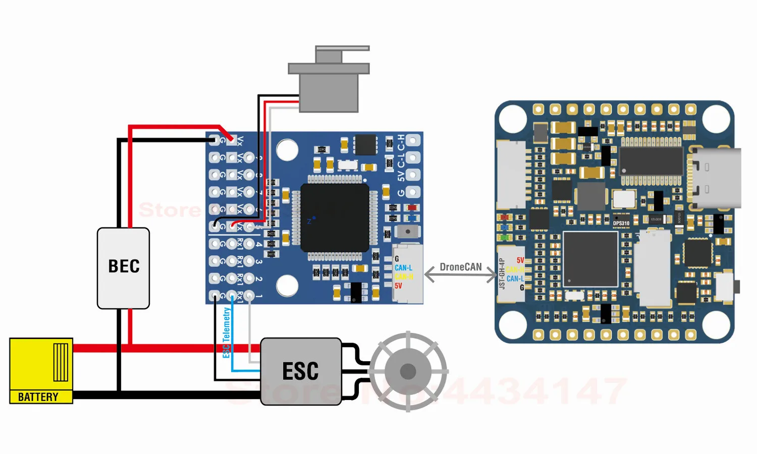
CAN-L4-PWM is an Adapter Node based on ArudPilot AP_Periph firmware.
Using this adapter to turn DShot capable ESCs into CAN ESCs, including full ESC telemetry. and turn PWM servos into CAN servos.
Specifications
MCU: STM32L431xC, 256KB Flash
1x CAN, DroneCAN Protocol
9x PWM outputs (8x Dshot)
- 1.5x UARTs
UART1, RX1
UART3, Tx3/ Rx3
ST debug, SWCLK & SWDIO
- LED
Blue, Fast blinking, Booting
Blue, Slow blinking, working
Red, 3.3V indicator
Input voltage range: 4.5~5.5V @5V pad/pin
Power consumption: 30mA
Operating Temperatures : -20~80 °C
“Vx” pads are for powering servos via external BEC. “Vx” is not connected to other components on this board.
“Rx1” pads are for ESC Telemetry, DO NOT connect ESC BEC output to Rx1 pad.
- Physical
1x JST-GH-4P(SM04B-GHS-TB) for CAN
Board Size: 32mm*25.4mm. 3.5g
Mounting: 20mm. Dia.3mm
3D file : CAN-L4-PWM_STEP.zip
- Firmware
ArduPilot AP_Periph MatekL431-Dshot
Update via DroneCAN GUI Tool
Packing
1x CAN-L4-PWM board
1x JST-GH-4P to JST-GH-4P 20cm silicon wire
SLCan Mode CAN1 > Parameters | Default Parameters | ||||
PWM | 1 | PA8 | TIM1_CH1 | OUT1_FUNCTION | 33 |
2 | PA9 | TIM1_CH2 | OUT2_FUNCTION | 34 | |
3 | PA10 | TIM1_CH3 | OUT3_FUNCTION | 35 | |
4 | PA11 | TIM1_CH4 | OUT4_FUNCTION | 36 | |
5 | PA15 | TIM2_CH1 | OUT5_FUNCTION | 51 | |
6 | PA2 | TIM2_CH3 | OUT6_FUNCTION | 52 | |
7 | PA3 | TIM2_CH4 | OUT7_FUNCTION | 53 | |
8 | PA1 | TIM2_CH2 | OUT8_FUNCTION | 54 | |
9 | PA6 | TIM16_CH1 | OUT9_FUNCTION | 55 | |
UART | RX1 | UART1 | Serial PORT 0 | ESC_TELEM_PORT | 0 |
TX3 RX3 | UART3 | Serial PORT 2 | USER | ||
ESC_PWM_TYPE | 7 | ||||
OUT_BLH_OTYPE | 6 | ||||
OUT_BLH_MAS | 15 | ||||
Parameters in Flight controller
CAN_D1_PROTOCOL = 1
CAN_P1_DRIVER = 1
CAN_D1_UC_ESC_OF = 4 (Plane 4.2.1 or newer)
CAN_D1_UC_ESC_BM = x
CAN_D1_UC_SRV_BM = x
BRD_SAFETYENABLE = 0 (if your flight controller doesn’t have safety pin)
Tutorial : Using MatekL431 adapters for PWM and DShot
CAN NODE L431
CAN-L431 is an Adapter Node based on ArudPilot AP_Periph firmware.
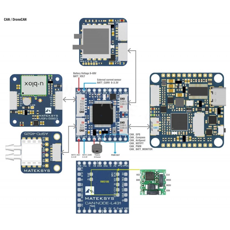
With this board, you can easily utilize the ArduPilot driver library to convert ArduPilot supported GNSS, Compass, Barometer,Airspeed sensor, and GPIO based (PWM, Buzzer/LED notify) peripherals to DroneCAN bus peripherals.
Specifications
MCU: STM32L431xC, 256KB Flash
CAN transceiver data rates up to 5 Mbit/s in the CAN FD fast phase
1x CAN, DroneCAN Protocol (2x GH-4P connectors in parallel)
- 3x UARTs
UART1, spare
UART2, MSP default, DFU
UART3, GPS default
- 1x I2C
for peripheral Airspeed sensor
for peripheral Barometer
for peripheral Compass QMC5883L
- 1x SPI
for peripheral RM3100
- 4x ADC
BATT_VOLT, PIN 5
BATT_CURR, PIN 6
BATT2_VOLT, PIN 15
BATT2_CURR, PIN 16
5x PWM outputs
1x GPIO with TIM16 for buzzer
ST debug, SWCLK & SWDIO
- LED
Blue, Fast blinking, Booting
Blue, Slow blinking, working
Red, 3.3V indicator
Input voltage range: 4.5~5.5V @5V pad/pin
Power consumption: 40mA
Operating Temperatures:-20~80 °C
- Physical
2x JST-GH-4P(SM04B-GHS-TB) for CAN
1x JST-GH-4P(SM04B-GHS-TB) for I2C
1x JST-GH-6P(SM06B-GHS-TB) for UART3+I2C
Board Size: 26mm*26mm*6mm. 3.7g
3D file : CAN-L431_STEP.zip
- Firmware
ArduPilot AP_Periph MatekL431-Periph, or MatekL431-Airspeed
Update via DroneCAN GUI Tool
Packing
1x CAN-L431 board
1x JST-GH-4P to JST-GH-4P 20cm silicon wire
1x JST-GH-6P to JST-GH-6P 20cm silicon wire
SLCan Mode CAN1 > Parameters | Parameters | |||
UART | TX1 RX1 | UART1 | Serial PORT 0 | USER |
TX2 RX2 | UART2 | Serial PORT 1 | MSP_PORT 1 | |
TX3 RX3 | UART3 | Serial PORT 2 | GPS_PORT 2 | |
I2C | SCL/SDA | PB13/PB14 | Baro SPL06 | Address 0x76 |
QMC5883L | Default parameters | |||
MS4525 | ARSP_TYPE 1 | |||
SPI1 | SCK, SO, S1, CS1 | RM3100 | ||
ADC | Vbat pad | PA0 | 0~69V | BATT_MONITOR 4 |
Curr pad | PA1 | 0~3.3V | BATT_CURR_PIN 6 | |
VB2 | PB0 | 0~3.3V | BATT_MONITOR 4 | |
Curr2 | PB1 | 0~3.3V | BATT2_CURR_PIN 16 | |
PWM | 1 | PA8 | TIM1_CH1 | OUT1 |
2 | PA9 | TIM1_CH2 | OUT2 | |
3 | PA10 | TIM1_CH3 | OUT3 | |
4 | PA11 | TIM1_CH4 | OUT4 | |
5 | PA15 | TIM2_CH1 | OUT5 | |
2812 LED | ||||
Buzzer | Bz- | Passive buzzer – | ||
5V | Passive buzzer + | |||
Disable GPS | GPS_TYPE 0 | |||
Disable compass | COMPASS_ENABLE 0 | |||
Disable Battery monitor | BATT_MONITOR 0 | |||
Disable MSP | MSP_PORT -1 | |||
Parameters in Flight controller
CAN_D1_PROTOCOL = 1
CAN_P1_DRIVER = 1
GPS_TYPE = 9 DroneCAN
COMPASS_TYPEMASK DroneCAN (Unchecked)
ARSPD_TYPE = 8 (DroneCAN)
NTF_LED_TYPE -> DroneCAN (Checked)
Tips
MatekL431-Periph firmware support I2C compass QMC5883L by default
If you connect other I2C compass to this board, you need to update it with this firmware via DroneCAN GUI or SLCAN mode in Mission Planner.